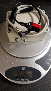
Here is an image of the Raspberry Pi box I used for a short trip in the Norwegian mountains.

Thats right, 212 grams or 7.5 oz. It has been revised a couple of times since then, but you get the idea.
How does this work? you might ask. I'm not going into the details of the Winlink system, you can find that at www.winlink.org if you are not familiar with the system. The beauty of the Pat client is that it can run as a web server on you computer, or in this case Raspberry Pi Zero W, that you connect to by Wi-Fi by setting up either your phone/tablet, or the Pi as a hot spot. Giving you an easy to use web mail like interface.
So what would you need to build something like this.
Hardware
- Raspberry Pi Zero W or 3B
- Micro SD card
- Some sort of power supply. This could be a 12v to usb converter if you plan on powering it with the same battery as you radio, or an usb powerbank of some sort. Please be aware og Ampere rating of the power supply, and possible RFI issues. Especially with cheap Chinese 12v to USB converters.
- A sound card. Chep usb dongles from ebay will work just fine. Remember OTG adapter if you plan on using it on a zero.
- A PC817 optocoupler and a 220 Ohm resistor (for ptt)
- A 3,3v to 5v TTL level converter if you plan on using the built in serial port on the Pi for rig control.
- Appropriate HDMI cable, mouse and keyboard for setup. It is possible to do it without, but i wont go into detail about that here. (TIP: Google Raspberry Pi wifi first boot, and Raspberry pi SSH first boot)
- Some sort of enclosure is recommended, especially if you plan on bringing it out doors.
- Connectors, plugs, wire, cable to your liking to connect the Pi to your radio.
Software.
- Raspbian operating system. https://www.raspberrypi.org/downloads/raspbian/ Both desktop and lite version will work just fine.
- piardopc tnc/modem http://www.cantab.net/users/john.wiseman/Documents/ARDOPC.html
- PAT Winlink client. www.getpat.io
- Rig control https://github.com/la5nta/pat/wiki/Rig-control
- Direwolf packet tnc https://github.com/wb2osz/direwolf
- Gpsd, for position data if you have a suiting gps. http://www.catb.org/gpsd/installation.html
- Screen ( sudo apt-get install screen )
- VNC
For software installation I refer you to the links above and Google.( Tip LA3QMA Is working on a piece of software to make setup as easy as pie. https://github.com/LA3QMA/PATPiBox )
Putting it together.
Once you have all the hardware collected and software installed and set up its time to play with the hardware. This is how i put it together.
I just soldered wires from the soundcard to a female trrs connector mounted on the box.
I find that using Tip for Tx and Ring for Rx audio makes things easier to remember. Sleeve is usually ground, so I'm following that standard, that leaves the second Ring for PTT.
I connect only the tip of the mic a headphones connector on the soundcard to the tx and rx line. Ground can most likely be used from anywhere. YMMW. I just connected pin 2 and 4 on the optocoupler It is important thou that the ground and ptt line is connected correctly on the PC817 optocoupler as both the diode and photo resistor side is polarized.
Then i made a TRRS to radio cable matching the connectors on my radio. See the user manual of your radio for how to hook up your cable.
Then i made a TRRS to radio cable matching the connectors on my radio. See the user manual of your radio for how to hook up your cable.
If you wish to use the Pi's internal serial port for rig control you will most likely want to shift the TTL voltage level form 3,3V to the more common 5V TTL level used in most modern rados. A cheap TTL level converter from E-bay wil do the trick.
Tip. The Pi3 and Zero W with built in bluetooth changed the name of the serial port ont the gpio pins from /dev/ttyAMA0 to /dev/ttyS0. It took me some time and frustration to realize this.
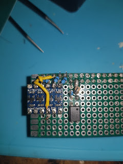
 I mounted everything on a pref board that I already had cut to match the pi zero in size. If you look really close you can see that I mounted the ptt circuit on th wrong pins, and had to move it one step to the left.
 I mounted everything on a pref board that I already had cut to match the pi zero in size. If you look really close you can see that I mounted the ptt circuit on th wrong pins, and had to move it one step to the left.
 PTT and serial port connected.
For clarity I used only yellow wires ;p
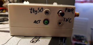
I also added an ACT led to the box. To do this add the following line to /boot/config.txt
dtparam=act_led_gpio=25
And connect a led (with an appropriate resistor ) to gpio 25
I also connected a momentary pushbutton to the power header, to be able to (re)boot with out disconnecting the power cable, and a RCA connector to the TV-out header.

 |
Software setup and testing.
Set up ARDOP: http://la4tta.blogspot.no/2018/04/setting-up-ardop-on-raspberry-pi.htmlSet up Pat: https://github.com/la5nta/pat/wiki/The-command-line-interface
For using the web gui from another device on the network, like your phone it is important to remove localhost from the http addr line. It should look like this.
"http_addr": ":8080",
Start ardop
Open a terminal or use ssh.Navigate to the folder where you downloaded piardopc.
Run with " ./piardopc -p gpio "
Start Pat
From another terminal window run " pat interactive --http "This starts Pat in interactive mode, and the http server.
Interactive mode lets you start and stop listeners and some other neat stuff. But that for another post.
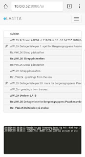
Test from your web browser.
 Open a web browser on a device connected to the same network as you pi.
go to [the ip adress of the Pi]:8080.
It should look something like this.
Try a connect just to be sure everything is working.
Once you are satisfied that everything is working set up your phone as a Wi-Fi hot spot. You will most likely find info on how to do this in your phones user manual, or Google. :)
Connect you Pi to this hot spot using your favorite method.
Alternatively you can set up your Pi as the Hot Spot and connect you phone to that, but I prefer the other way around because once the pi is set up as a hot spot, it can connect to other WiFi networks for updates and other Internet stuff.
Once connected I use Juice to SSH into the Pi. Start screen to be able to run multiple processes in one terminal. And also to be able to retrieve these processes if disconnected for some reason.
I start rig control first.
" rigctl -m 120 -r /dev/ttyS0 -s 4800 "
Then CTRL-a c to open a new window where i start ARDOP or DIREWOLF tnc
Then CTRL-a c to open a new window where i start Pat
" pat interactive --http "
If you want you can start the ardop listener with the command
" listen ardop " this makes Pat listen for incoming p2p sessions.
I think thats it.
Leave comments and questions below or in the Pat forum.


